Rich text
There are several elements which integrate to construct and operate the project.
There are several elements which integrate to construct and operate the project.
The upper reservoir will be a rockfill “gully dam” constructed behind the southeastern ridge of Mount Walker, over 250 metres (m) above Lake Lyell. Its working storage volume will be 5.3 gigalitres (GL).
Lake Lyell will be the project’s lower reservoir; so no new lower reservoir or dam will need to be constructed. The lake was dammed in 1982 (Lilyvale Dam) and is filled by natural flow from the Coxs River and Farmers Creek. Its storage volume is 33.5 GL. The target PHES operating level will be between 781 m Australian Height Datum (AHD) to 784.5 m AHD. The project may run a full or part cycle over the day or week, and this may see the Lake Lyell water level change by differing amounts depending on the needs of the electricity network.
The inlet/outlet structure will be located within the lowest point of the upper reservoir to deliver water up to the upper reservoir through the power waterways during pumping mode and release water to the power waterway during generation mode.
The inlet/outlet structure will be located within the lower reservoir (Lake Lyell) in Farmers Creek Arm to draw water up to the upper reservoir through the power waterways during pumping mode and release water from the power waterway during generation mode.
The power waterways will provide a connection between the reservoirs through which water will flow. They will comprise:
The power waterways will be lined with a combination of steel and concrete.
Located in an underground cavern near the base of the headrace tunnel, the powerhouse will contain the two reversible pump-turbines, control valves, generators, transformers and a variety of electrical equipment.
Access to the power waterways and the powerhouse will be attained via access tunnels and portals, which will include:
Each tunnel will have a portal/entrance at the surface, with a surface area of approximately 100 m x 50 m.
One vertical underground surge shaft will be located downstream of the powerhouse and connected to the tailrace tunnel waterway and to the surface. The surge shaft will be around 11m diameter.
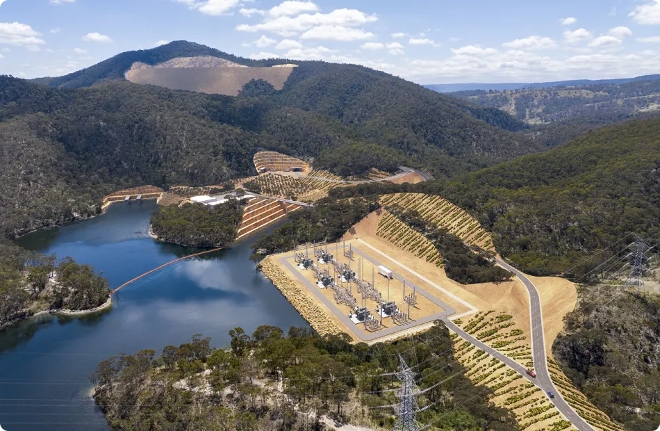
A HV switchyard will contain the electrical equipment required to facilitate the connection between the project and the existing transmission network. A short transmission connection will be constructed to connect the HV switchyard to the nearby existing Wallerawang to Sydney South 330 kV transmission line. An underground cable will connect the powerhouse main transformers and the switchyard.
The project area will be accessed via Sir Thomas Mitchell Drive, which will undergo upgrades to allow project-related vehicles safe access. Upgrades to the intersection of Sir Thomas Mitchell Drive and Magpie Hollow Road is required. Upgrades to the intersection of Great Western Highway and Magpie Hollow Road is also required to allow transport of the largest of the oversized equipment to site.
Existing access roads within the project area will be upgraded as required and new ones will be constructed to allow access to key areas within the project area.
Temporary bridges will be established across Farmers Creek to provide construction access to the northern part of the project area. One will provide access to the tunnel portals and the other will provide access to the upper reservoir.
A further temporary bridge will be established across Farmers Creek to allow the construction of the western coffer dam at the lower inlet/outlet area.
A permanent bridge will be established to cross the diverted path of Farmers Creek arm of Lake Lyell. This bridge will provide operational access to the upper reservoir and powerhouse.
The Farmers Creek arm of Lake Lyell will be diverted near the lower inlet/outlet structure. This will be undertaken to mitigate risks to project operation from flooding and the risks associated with sedimentation and to improve the overall constructability of the project. The lake diversion will be an open channel and designed to allow continued upstream and downstream passage of fish and aquatic fauna.
The part of the diverted lake area east of the lower inlet/outlet structure will be used for flood protection and access to the tunnel portals and housing spoil generated on-site. The part west of the lower inlet/outlet will be deepened and then rejoined with Lake Lyell.
The administration building will act as a control centre, staff centre and office. The building itself will be approximately 20 m x 15 m in size with a 500 m2 sealed carpark with kerb and gutter. The approximately 28 m x 20 m maintenance workshop/store will be located adjacent to the administration building.
To assist ongoing design refinement, geotechnical and geophysical surveys and investigations are proposed within the disturbance footprint.
A workers accommodation village is proposed to house up to 500 workers (referred to as an accommodation camp). The accommodation camp preferred location is lake side on land north of Magpie Hollow Road, South Bowenfels. An alternate location is also being considered in Lithgow town on land at the Pottery Estate. Subject to evaluation and approvals only one camp location would be built. The configuration of the accommodation camp will be confirmed during detailed design however is expected to include accommodation units/rooms, camp kitchen, first aid facility, gym and/or recreation room, laundry, and carparking, as well as a pontoon for lake access.
The detailed design of the workers accommodation village will also be informed by a desire for a permanent or temporary facility.
A level pad will be constructed to the south of Farmers Creek to house the administration and main site compound.
A level pad will be constructed on the north side of Farmers Creek below the upper reservoir location to provide a staging location for construction facilities and servicing of equipment during the construction of the upper reservoir.
A stormwater basin will be constructed to the south of the upper reservoir laydown pad. Additional smaller basins may be constructed within the site.
A batch plant will be established within the HV switchyard pad. The approximate footprint including stockpiles will be 100 m x 100 m. As construction progresses, the batch plant will be relocated to the lake infill area. An additional batch plant may be established on the upper reservoir laydown pad if required.
Two cofferdams will be utilised for the diversion of Lake Lyell. The downstream cofferdam will be temporary, while the upstream cofferdam will remain permanently. The cofferdams will improve constructability by excluding water from work areas. A water monitoring well will be installed within the two cofferdams to monitor water for reuse or treatment.
Explosives for the drill and blast works will be stored at a location on site that complies with all relevant standards and guidelines.
Large volumes of spoil will be generated, primarily through:
This spoil will predominantly be utilised for construction of:
Spoil that cannot be re-used for the construction of these elements will be placed in engineered spoil stockpiles to the north and south of Farmers Creek. Excess spoil will be transported offsite to a facility approved to accept the material.
EnergyAustralia and EDF power solutions Australia recognise that we operate and plan for the energy transition on the traditional Country of the Wiradjuri peoples and we respect and acknowledge their continued connection to Country and culture.